|
Introduction
Overview
Computer requirements
Packet Engine Pro
Configure AGWPE
Download and Install
Basic AGWPE Setup
2 Radio Setup
2 Card Setup
Sound Device Setup
Basic Device Settings
Rename Sound Device
Additional Settings
Using the Tuning Aid
Problems?
Program Behavior
Receiving
Transmitting
Connections
Firewalls
AGWPE Features
AGWPE on a Network
Baud Rates & Modes
Remote Control
TCP/IP Over Radio
Tips and Tricks
Traffic Parameters
Compatible Programs:
Setup Help
Radio Interface
Getting Started
Kits and Pre-assembled
USB SignaLink
Receive Audio Cable
Transmit Audio Cable
PTT (TX Control) Cable
2 Radio Modification
About Packet
Packet Overview
Exchange Modes
TNCs and AGWPE
What
To Do with Packet
Common Frequencies
Frame Headers
Further Reading
|
|
AGWPE can use one
sound card to interface with TWO different radios at the same time. It does this by using the left and right stereo channels of the
sound card, in effect making the sound card a "dual port" TNC
(see the
AGWPE: 2 Radio Setup page on this site
for more information about configuring AGWPE for this feature.)
This means you can have 2 different packet programs
running, each one sending and receiving data with a different radio on a
different frequency. If you use WinAPRS, UI-View, or APRSplus, you could
have one radio tuned to the local APRS frequency and the other to
the local DX cluster frequency or to an HF APRS frequency.
To run a second radio with the sound card, you'll
need to use:
- for PTT control, the DTR pin on the
COM port or pins 8 or 9 on the LPT port
- for TX and RX audio, the ring of
your stereo
sound card jacks
Note this dual radio feature will not work if use the
Microphone jack of the sound card (for RX
audio), since that jack typically has mono only
input and not stereo. You must use the LINE IN jack if you want
to interface to two radios.
Here's the pin and plug assignments for "dual
port" sound card use:
|
AGWPE
Port
|
Card
Channel
|
Stereo
Plug
|
PTT
Pin
|
DB9 serial
pin # GND
|
DB25 serial
pin # GND
|
DB25 Parallel*
pin # GND
|
|
1
|
Left
|
Tip
|
RTS
|
7
|
5
|
4
|
7
|
2 or 3
|
18-25 (any)
|
|
2
|
Right
|
Ring
|
DTR
|
4
|
5
|
20
|
7
|
8 or 9
|
18-25 (any)
|
NOTE 1:
Do not use the
computer ground pin unless:
- You are wiring the shield to the computer ground instead of
the radio ground (don't wire to both!); or
- You are using an isolation transformer and need to wire one
side to computer ground.
NOTE 2: If you are running Windows
XP/2000/NT, you can not use the LPT/parallel/printer port for
PTT control. You must use the serial port.
The parallel port option will work only with Windows 95, 98 and ME in
AGWPE. If you use Windows XP, and want to use the parallel port for PTT
control, you can purchase
Packet
Engine Pro.
1. RX and TX Audio Cables
The
RX Audio Cable and
TX Audio Cable pages of this site describe
how to make cables for a radio which would use the left channel
of the sound card and Port 1 in AGWPE. Such cables uses the tip of the stereo TX and RX plugs
and the RTS pin on the
serial/parallel port plug for PTT control. If you already have a set of cables, they are probably wired
in this manner.
If you want to use a second radio with the sound card, you would attach
a second audio cables to the
ring of the stereo plugs (the right
channel of the card or port 2 in AGWPE).

Here are two different
approaches for the audio cables:
- Cheaper but harder -- wire it
yourself:
Using the cable schematics on the
RX Audio
Cable and
TX Audio Cable pages, add a second cable
(single wire shielded) to
each sound card plug. The single insulated wire will run from the unused ring
(middle conductor) of the sound card plug to the proper pins (RX or
TX) on radio #2. The shielding should attach to the ground on the radio but
NOT attach to the ground
on the computer.
You'll need to make this alteration for both
the RX and TX Audio plugs. You'll also need
to add a separate attenuation circuit (see
TX
Audio Cable) for the second TX audio
cable.
-
Easier but a little more
expensive -- buy two "Y" adapters (Bill's, WB2JAR, idea):
Rather than try to squeeze the wires from both radios into the same sound card
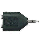
plug, use a "Y" adapter. The "Y" plugs into the sound card jack and will accept
two sets of audio cables, one for each radio, into the arms of the 'Y
|
 Separates
left and right-channel signals. Has a 3.5mm stereo phone
plug & two 3.5 mm mono phone jacks.
|
Bill suggests Radio Shack part
#274-375 ($3.59 each) which
even does the channel separation for you! Of course,
you'll need 2 of these adapters -- one for the sound card's
LINE IN jack (RX audio) and one for the sound card's LINE
OUT jack (TX audio).
These adapters accept simple mono
plugs into their jacks. No need for stereo/3 line cables
and no need to worry about "tip" or
"ring" assignments. The adapter handles
that.
The silver plated
jack on the 'Y' is used for the cable coming from radio
#1. It's wired to the tip
of the adapter's stereo plug and provides the connection to
the left channel of the sound
card (AGWPE Port 1).
The gold
plated jack on the 'Y' is for the cable coming from radio
#2. It's wired to the ring
of the adapter's stereo plug and provides the connection to
the right channel of the sound
card (AGWPE Port 2).
|
If you come up with still another method for the audio cables,
let
me know.
2. PTT Cable
To control the PTT on the second radio, you'll need
to add a wire that will run from the DTR pin
of the serial or printer port to the radio and includes a second PTT circuit (see
PTT Control cable page).
You might try one of these
methods:
- A. Wire both PTT cables into
the same DB25 (or DB9?) connector. Here's a
diagram that Bill, WB6JAR, created for a DB25 for the printer port. (I don't know if you
could shoehorn all of this into a DB9 for the serial port.) To simplify the soldering,
he broke off some of the pins going out of the DB25 (that would
normally plug into the computer) and used the resulting stubs inside
the DB25 as solder points. The downside of 2 cables into one DB
connector is that, if you want to use
just one radio, the PTT cable for the second radio will always be
attached to the DB25 and this might be cumbersome.
Click on the graphic for a larger view. If you do, use your
browser's BACK button to return to this page.
 Click to enlarge
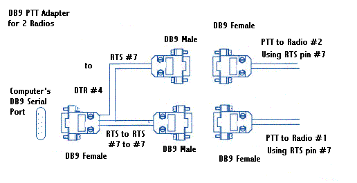
- B. Make a two cable adapter from DB9 plugs.
This "Y" arrangement allows you to split the RTS and DTR signals to
different DB9 male plugs. You can then plug
standard PTT control cables with DB9 female
jacks into the DB9 males plugs. (Could also work with the LPT
port.)
Solder the DTR wire to the RTS pin in the DB9 male for
radio #2. This allows you to use either radio's PTT control cable on
either male plug, since both male plugs will be sending the PTT signal on pin #7, even though radio #2 is really getting its signal from the
DTR pin on the computer.
This "Y" arrangement also lets you easily remove the second PTT cable
if you're not using it.
Hint: Put a label on each DB9 to specify if it is for radio port 1
or 2.

Don't forget to
change
AGWPE's settings to a "dual port"
|